→ 상품 상세 정보 : D880C Shutter Driver
Overview
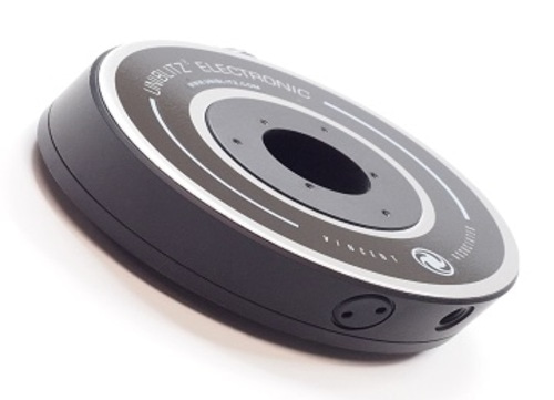
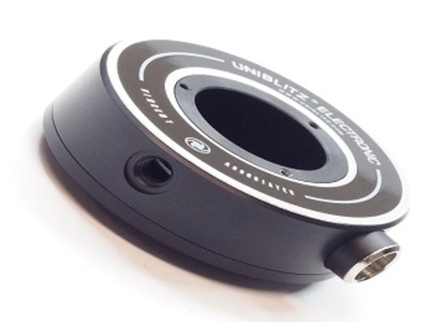
The Uniblitz D880C is an open-frame, uni-stable shutter driver utilizing constant current control which has shown to increase shutter life time over standard capacitive discharge types. It is well-suited for integration into OEM applications when paired with a large selection of Uniblitz shutters (all compatible shutter devices will require the “E” option (“For use with VED24 or D880C”) in order to properly operate with the D880C).
Simple external connections to the D880C are made through the pluggable input/output screw terminal connector. This enables the D880C to be quickly connected/disconnected without having to remove any wires connected to the terminal block.
Control of the D880C requires that the user supplies a TTL (5V) logic level to the trigger input or connecting a mechanical or electronic switch between the trigger input and +6.75 VDC.
See the D880C User Manual for additional information regarding this device. The D880C is RoHS compliant.
What’s Included
- D880C Shutter Driver
- Manual (included on flash drive)
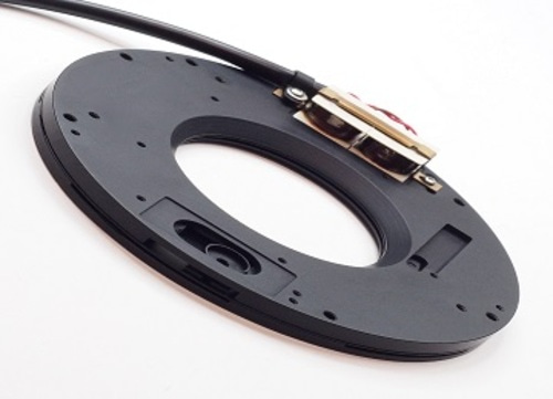
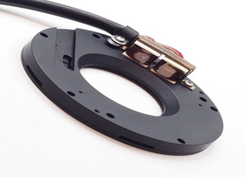
- 710P Shutter Interconnect Cable
A power supply is not included with this device.
Shutter Compatibility
| VS | LS | CS | DSS | TS | NS | XRS |
|---|---|---|---|---|---|---|
| VS14 1 | LS2 1 | CS25 1 | XRS6 1 | |||
| VS25 1 | LS3 1 | CS35 1 | XRS14 1 | |||
| VS35 1 | LS6 1 | CS45 1 | XRS25 1, 2 | |||
| CS65 1 |
1 Will require “E” option (“For use with VED24 or D880C”) for D880C compatibility.
2 Will require two drivers for operation.
Don’t see your device listed above? Please contact us for information regarding the compatibility of other shutter devices.
Specifications
| System Characteristics | |
|---|---|
| Repeat Exposure | Minimum time between exposures is determined by shutter used and open close pulse duration. |
| Shutter Drive | Continuously variable frequency of exposures from DC to the shutter in operation maximum rate. |
| Pulse Current: 1.2A | |
| Hold Current: 300mA | |
| General | Size (HWD) 1.00 x 3.20 x 4.00 inches (25.4 x 81.2 x 101.0 mm) |
| Weight 3.00 oz (0.09 Kg) | |
| Power input: +24VDC at 1.5A (user supplied) | |
| RoHS Compliant | |
Board Mechanical Layout
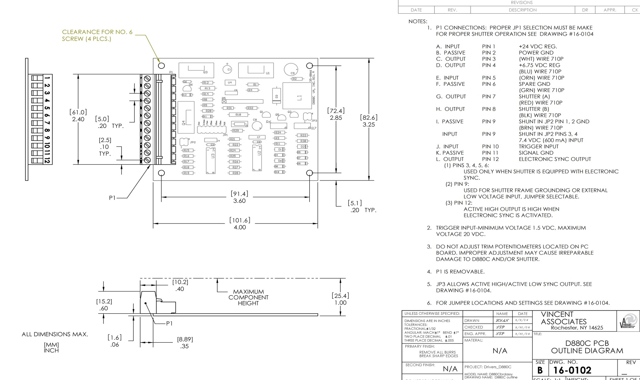
| P1 Connections | ||
|---|---|---|
| Pin 1 | Input | +24 VDC (Regulated) |
| Pin 2 |
Passive | Power Ground |
| Pin 3 | Output | Sync control; White wire of 710P |
| Pin 4 | Output | +6.75 VDC (Regulated); Blue wire of 710P |
| Pin 5 | Input | Sync control; Orange wire of 710P |
| Pin 6 | Passive | Sync Ground; Green wire of 710P |
| Pin 7 | Output | Shutter (A); Red wire of 710P |
| Pin 8 | Output | Shutter (B); Black wire of 710P |
| Pin 9 | Passive | Ground when shunt in JP2 Pins 1,2; Brown wire of 710P |
| Pin 10 | Input | 7.4 VDC (600 mA) input when shunt in JP2 Pins 3,4 |
| Pin 11 | Input | Trigger Input |
| Pin 12 | Passive | Signal Ground |
| Pin 13 | Output | Electronic sync output |
Notes
- P1 connections: Proper JP1 selection must be made for proper shutter operation. Please see “Jumper Selections” below.
- Pins 3, 4, 5, 6: Used only when shutter is equipped with electronic sync.
- Pin 9: Used for shutter frame grounding or external low voltage input, jumper selectable.
- Pin 12: Active-high or active-low output when electronic sync is activated, jumper selectable.
- Pin 10: Trigger input: Minimum voltage 1.5 VDC, maximum voltage 20 VDC, active-high only. P1 plug is removable.